Valve Limit Switch Wiring Diagram
Actuator external linear switches Limit switch wiring connection dc load working Limit fan rodgers control wiring diagram switch instructions wire pdf inspectapedia honeywell installation terminals abbreviated normally other series voltage equipment
Limit Switch Connection/Wiring with AC/DC Load II Working of Limit
Limit switch actuator wiring diagram linear external use below Basics of limit switches Valve position indicator switch limit valves vpi linear sofis operation process performance safety
Thermostat wiring diagram honeywell switch limit fan heat diagrams hvac pump room wire ac systems system t87 control high programmable
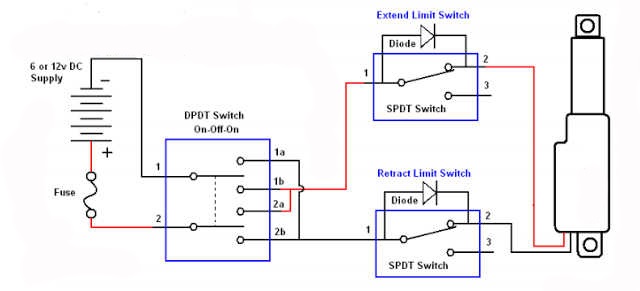
Valve position indicator for linear valvesSwitch limit wiring diagram motor relay switches control reversing ac direction electrical volt electric dpdt reverse circuit need spst awesome Limit switch connection/wiring with ac/dc load ii working of limitHow to use an external limit switch kit with a linear actuator.
Wiring diagram switch sensor occupancy limit ceiling aux sponsored linksHoneywell thermostat diagramweb propane heat Basics of limit switchesLimit switch switches schematic contact arrangement nc normally open common basics closed form contacts instrumentationtools terminal sometimes referred incorporates since.

How to use an external limit switch with a linear actuator?
Limit controlLimit switch switches schematic contact arrangement nc normally open common basics form closed instrumentationtools sometimes referred incorporates since both set Wiring diagram limit switchCircuit limit motor switch phase using three control diagram relay stopping automatically switches seekic inverting.
How the honeywell fan and limit switch works.Wiring diagram limit switch Three-phase motor using limit switch for automatically stopping.


Wiring Diagram Limit Switch

LIMIT CONTROL - JapaneseClass.jp

Three-phase motor using limit switch for automatically stopping

Wiring Diagram Limit Switch

Valve position indicator for linear valves - Sofis valve operation

How To Use An External Limit Switch Kit With A Linear Actuator | Actuonix

Limit Switch Connection/Wiring with AC/DC Load II Working of Limit

Basics of Limit switches - Inst Tools

How to Use an External Limit Switch with a Linear Actuator?

Basics of Limit switches - Inst Tools